Audio Reference
1. Audio Input (AI)
1.1. Input Interface Type
There are the interfaces supported by AI. Please refer the table below to get the specific info.
Table 1-1 Specification
| Type | Max channels | Sampling rate | Sampling depth | Sound channel |
|---|---|---|---|---|
| amic | 3 | 8/16/32/48 kHz | 16bit | STEREO/MONO |
| dmic | 4 | 8/16/32/48 kHz | 16bit | STEREO/MONO |
| I2s | Standard 2 channels, TDM 8 channels | 8/16/32/48 kHz(provided mclk) | 16bit | STEREO/MONO |
| linein | 3 | 8/16/32/48 kHz | 16bit | STEREO/MONO |
1.2. Device ID
Different device ID represent different interface type when AI initialize.
| Device ID | Type |
|---|---|
| AI_DEV_ID_ADC_0_1 (0) | 2-channels amic |
| AI_DEV_ID_DMIC (1) | dmic |
| AI_DEV_ID_I2S_RX (2) | I2s |
| AI_DEV_ID_LINE_IN (3) | Line in |
| AI_DEV_ID_ADC_2 (4) | 1-channel amic |
| AI_DEV_ID_ADC_0_1_2 (5) | 3-channels amic |
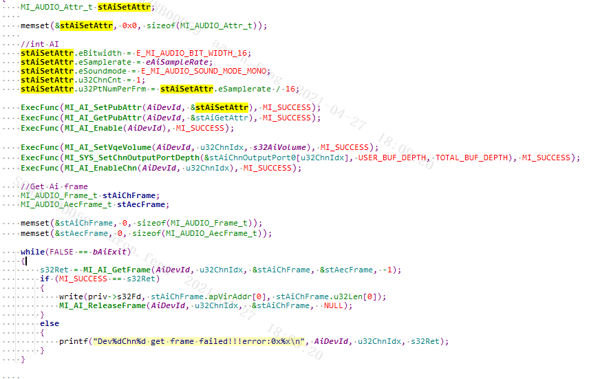
1.3. Amic Usage Scenarios
-
1-channel amic
It is mainly used in building intercom to collect 1-channel sound to realize outdoor and indoor intercom.
Confirm which group the amic connected before use.
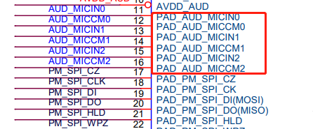
The corresponding device ID and channel index are as follows.
Pin Device ID Channel Index PAD_AUD_MICIN0 0/5 0 PAD_AUD_MICIN1 0/5 1 PAD_AUD_MICIN2 ⅘ 2 Reference demo:
-
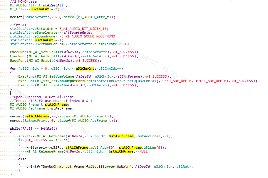
2-channels amic
It is mainly use in smart phone two-way collection to collect and transmit audio for handle and headphone.
Confirm which group the amic connected before use. The corresponding device ID and channel index are as follows.
Pin Device ID Channel Index PAD_AUD_MICIN0 & PAD_AUD_MICIN1 0/5 0 & 1 Reference demo(Collect two MONO data separately):
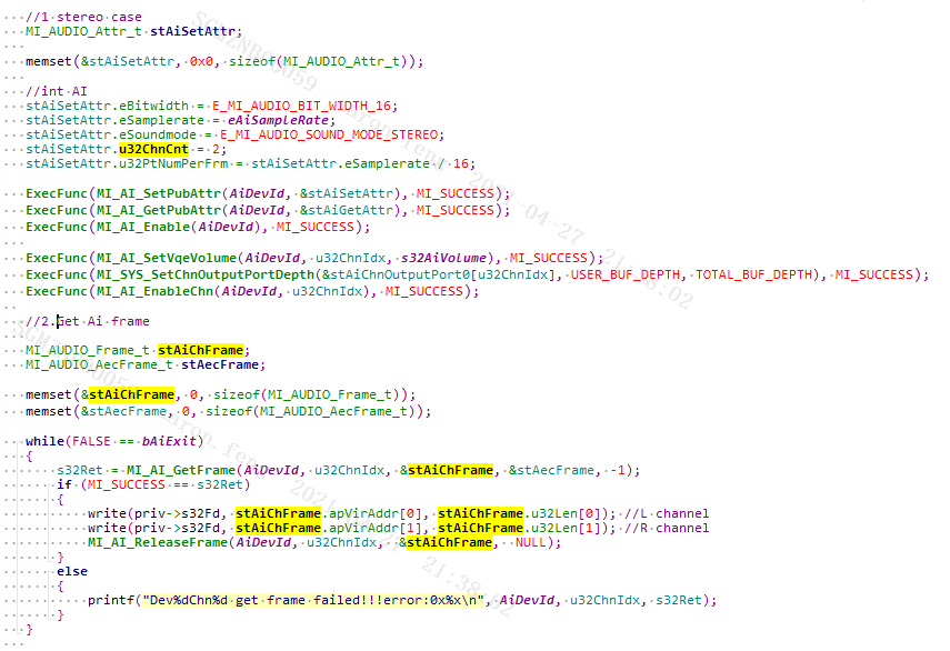
If you need to collect the data of L/R stereo separately, the corresponding relationships of pin, device ID and channel index are as follows:
Pin Device ID Channel Index PAD_AUD_MICIN0 & PAD_AUD_MICIN1 0/5 0 Reference demo:
-
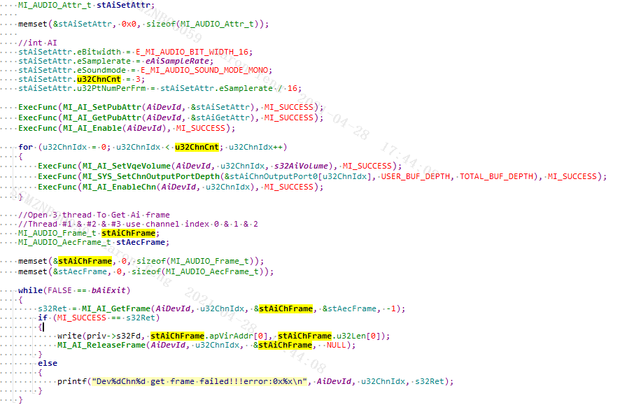
3-channels amic
It is mainly use in smart phone to collect audio for handle, headphone and headset. The corresponding relationships of pin, device ID and channel index are as follows:
Pin Device ID Channel Index PAD_AUD_MICIN0 & PAD_AUD_MICIN1 5 0 & 1 Reference demo:
1.4. Dmic Usage Scenarios
-
Configure pin to dmic mode
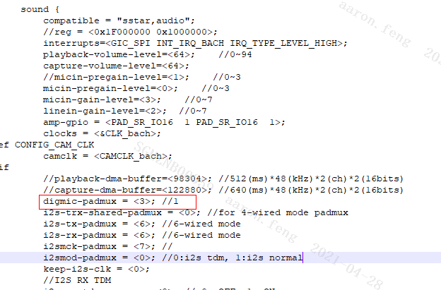
Confirm which set of pin is taking effect before use dmic, then configure digmic-padmux to the corresponding mode in
pioneer3.dtsi.The following dtsi config is corresponding to PAD_KEY6 (D1) & PAD_KEY7 (D0) & PAD_KEY8 (CLK) used in evaluation board.
-
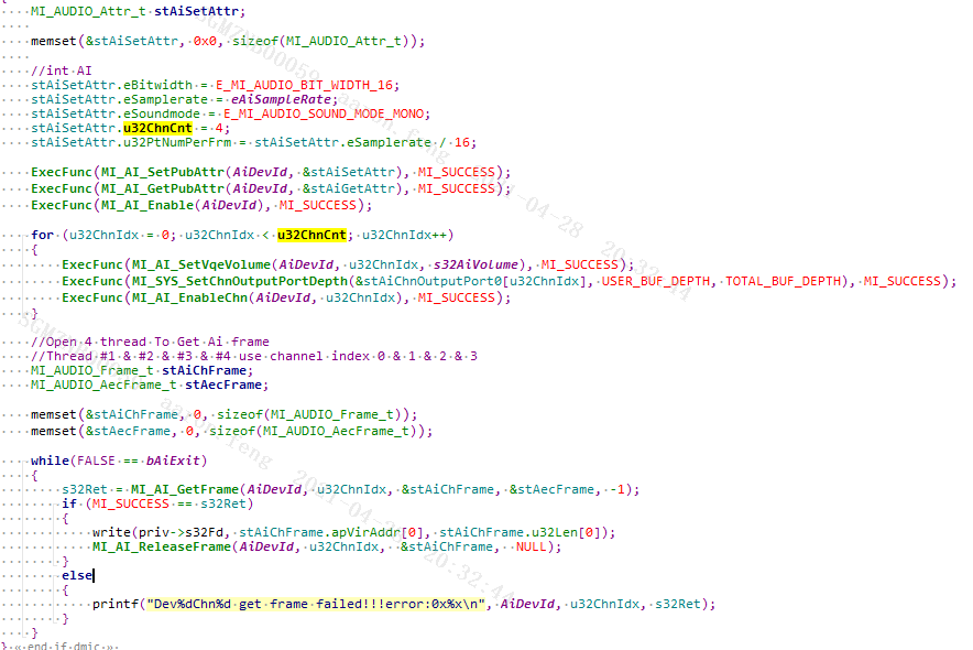
4-dmic
AI_DEV_ID_DMIC(1) is the device ID no matter 2dmic is used or 4dmic, and ChannelCount determines how many channels of audio need to be collected.
Reference demo:
1.5. I2s RX Usage Scenarios
-
I2s rx pin config
Confirm which set of pin is taking effect before use i2s rx, then configure the corresponding mode in PADMUX.
The following config is corresponding to PAD_GPIO3 & PAD_GPIO4 & PAD_GPIO5 used in evaluation board.
<PAD_GPIO3          PINMUX_FOR_I2S_RX_MODE_6      MDRV_PUSE_I2S_WCK>,
<PAD_GPIO4          PINMUX_FOR_I2S_RX_MODE_6       MDRV_PUSE_I2S_BCK>,
<PAD_GPIO5          PINMUX_FOR_I2S_RX_MODE_6       MDRV_PUSE_I2S_SDI>,
Refer to HW CheckList for the correspondence between pin and mode.
-
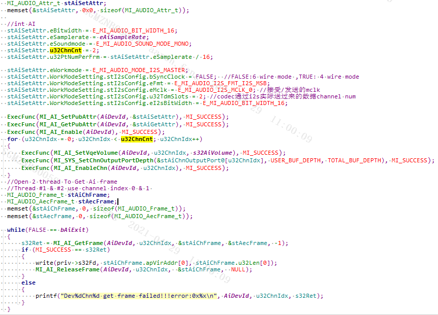
2-channels i2s
Reference demo:
-
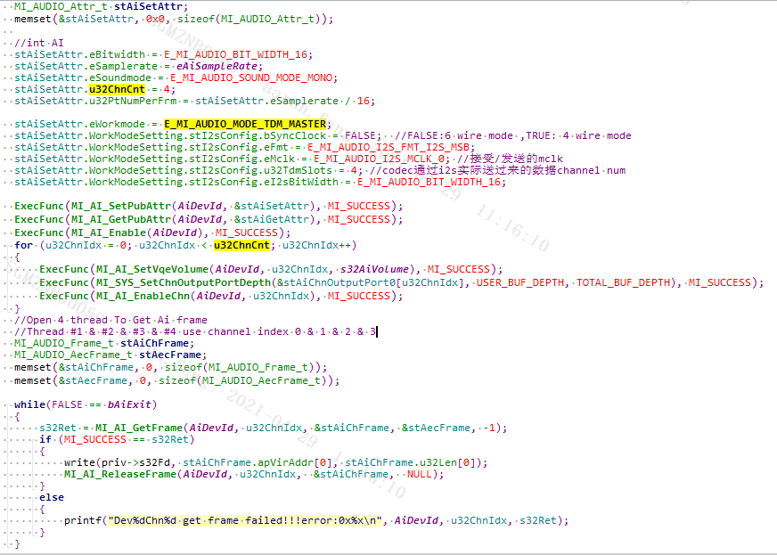
TDM i2s
Use TDM i2s when receiving more than two channels of i2s data.
Reference demo(take 4-channels as an example):
1.6. Line In Usage Scenarios
The use of Line in is the same as amic, except that there is a difference in setting Gain. For details, please refer to AI API.
2. Audio Output(AO)
2.1. Output Interface Type
| Type | Max channels | Sampling rate | Sampling depth | Sound channel |
|---|---|---|---|---|
| Line out | 2 | 8/11.025/12/16/22.05/32/44.1/48kHz | 16bit | STEREO/MONO |
| I2s tx | 2 | 8/16/32/48 kHz(provide mclk) | 16bit | STEREO/MONO |
| HeadPhone | 1 | 8/11.025/12/16/22.05/32/44.1/48kHz | 16bit | MONO |
2.2. Device ID
| Device ID | Type |
|---|---|
| AO_DEV_ID_DAC0_1 (0) | 2-channels Lineout |
| AO_DEV_ID_I2S_TX (1) | I2s |
| AO_DEV_ID_DAC0 (2) | 1-channel Lineout |
| AO_DEV_ID_DAC1 (3) | 1-channel Lineout |
| AO_DEV_ID_HEADPHONE (4) | Headphone |
| AO_DEV_ID_LINEOUT_MIX_ADC2_AND_HEADPHONE (5) | Output after Lineout mixed with headphone(voip sidestone) |
| AO_DEV_ID_LINEOUT_AND_HEADPHONE (6) | 2-channels Lineout and headphone output the same data at the same time |
2.3. Lineout Usage Scenarios
-
Lineout Amp config
It supports two-channel Line out dual-channel output and single-channel DAC0/DAC1 attribute control.(such as volume adjustment, mute/unmute, etc.)
-
In Line out mode, AoChn = 0 controls the left channel, AoChn = 1 controls the right channel.
-
According to the HW layout, the method of configuring amp_gpio is as follows
-
Modify the sound device tree node amp-gpio in
kernel\arch\arm\boot\dts\pioneer3.dtsi, and set PAD_SR_IO15/PAD_SR_IO16 to the left/right channel of amp_gpio to control the pin, and the default value is 1.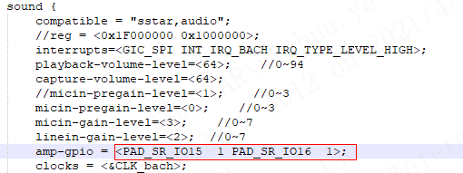
-
Set PAD_SR_IO15/PAD_SR_IO16 to MDRV_PUSE_AIO_AMP_PWL/MDRV_PUSE_AIO_AMP_PWR in
kernel\arch\arm\boot\dts\pioneer3-ssc020a-s01a-demo-camera-padmux.dtsi(Open*_padmux.dtsiused by config according to the actual situation)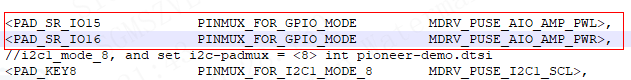
-
-
-
1-channel Lineout
Confirm which pin is taking effect before use Lineout.

Pin Device ID PAD_AUD_LINEOUT_L0 AO_DEV_ID_DAC0 (2) PAD_AUD_LINEOUT_R0 AO_DEV_ID_DAC1 (3) Reference demo:
-
2-channels Lineout
-
When 2-channels L/R using together, the corresponding relationships between Pin and Device ID are as follows.
Pin Device ID PAD_AUD_LINEOUT_L0 & PAD_AUD_LINEOUT_R0 AO_DEV_ID_DAC0_1 (0) Reference demo:
-
2-channels Lineout using independent
Use DeviceID (AO_DEV_ID_DAC0 & AO_DEV_ID_DAC1) on the basis of 1-channel Lineout using.
-
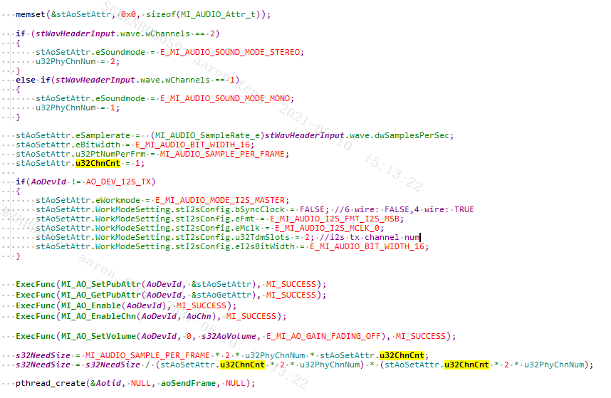
2.4. I2s Tx Usage Scenarios
-
I2s Tx pin configure
Confirm which set of pin is taking effect before use i2s rx, then configure the corresponding mode in PADMUX.
The following config is corresponding to PAD_GPIO3& PAD_GPIO4 and PAD_GPIO5 used in evaluation board.
<PAD_GPIO6          PINMUX_FOR_I2S_TX_MODE_6       MDRV_PUSE_I2S_SDO>,
<PAD_GPIO7          PINMUX_FOR_I2S_TX_MODE_6       MDRV_PUSE_I2S_BCK>,
<PAD_GPIO8          PINMUX_FOR_I2S_TX_MODE_6       MDRV_PUSE_I2S_WCK>,
Refer to HW CheckList for the correspondence between pin and mode.
-
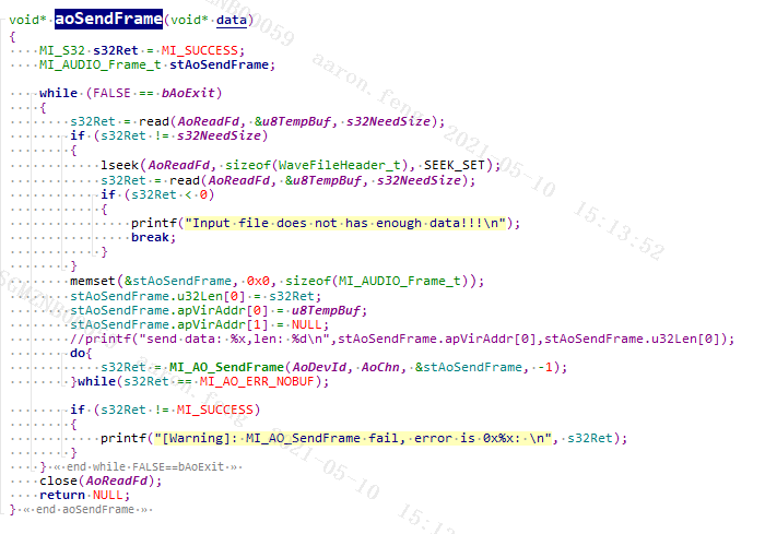
2-channels i2s tx
Reference dome: